Series 1 Water Pump
This practical guide details the step-by-step rebuild process for the Series 1 Land Rover water pump. It covers disassembly, inspection, machining, bearing installation, drive flange assembly, mechanical seal fitting, impeller assembly, and final checks. The guide is workshop-focused, highlighting common issues such as corrosion and bearing failure, and includes notes on dimensional settings for different pump variants. It is intended for those restoring original pumps, especially given the scarcity of quality replacements and known fitment challenges with aftermarket units.
Component Overview
Component
Series 1 Water Pump
Vehicle / Engine
Series 1
Original Manufacturer
Land Rover
Common Failures
Bearing failure, dry rumbly or squealing bearings, leaks, and excessive corrosion.
Why Rebuild Instead Of Replace
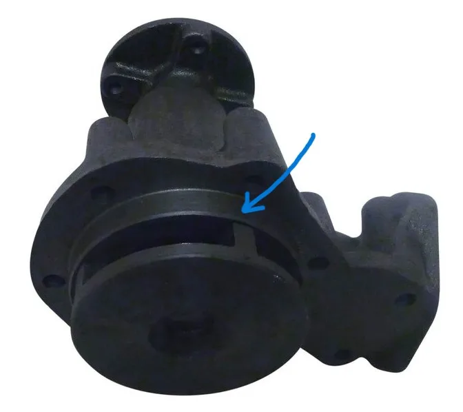
Original good quality pumps are no longer available, leaving only cheaper Chinese-made alternatives. A major issue with pumps for the Series 1 2L motor is that the pump body can foul on the aluminium timing chain cover. While this can be remedied by grinding the fouling area on the pump, rebuilding the original pump is preferred.
Job Breakdown
Step 1
Disassembly
Purpose
Remove the impeller and extract the bearing and drive flange.
Method
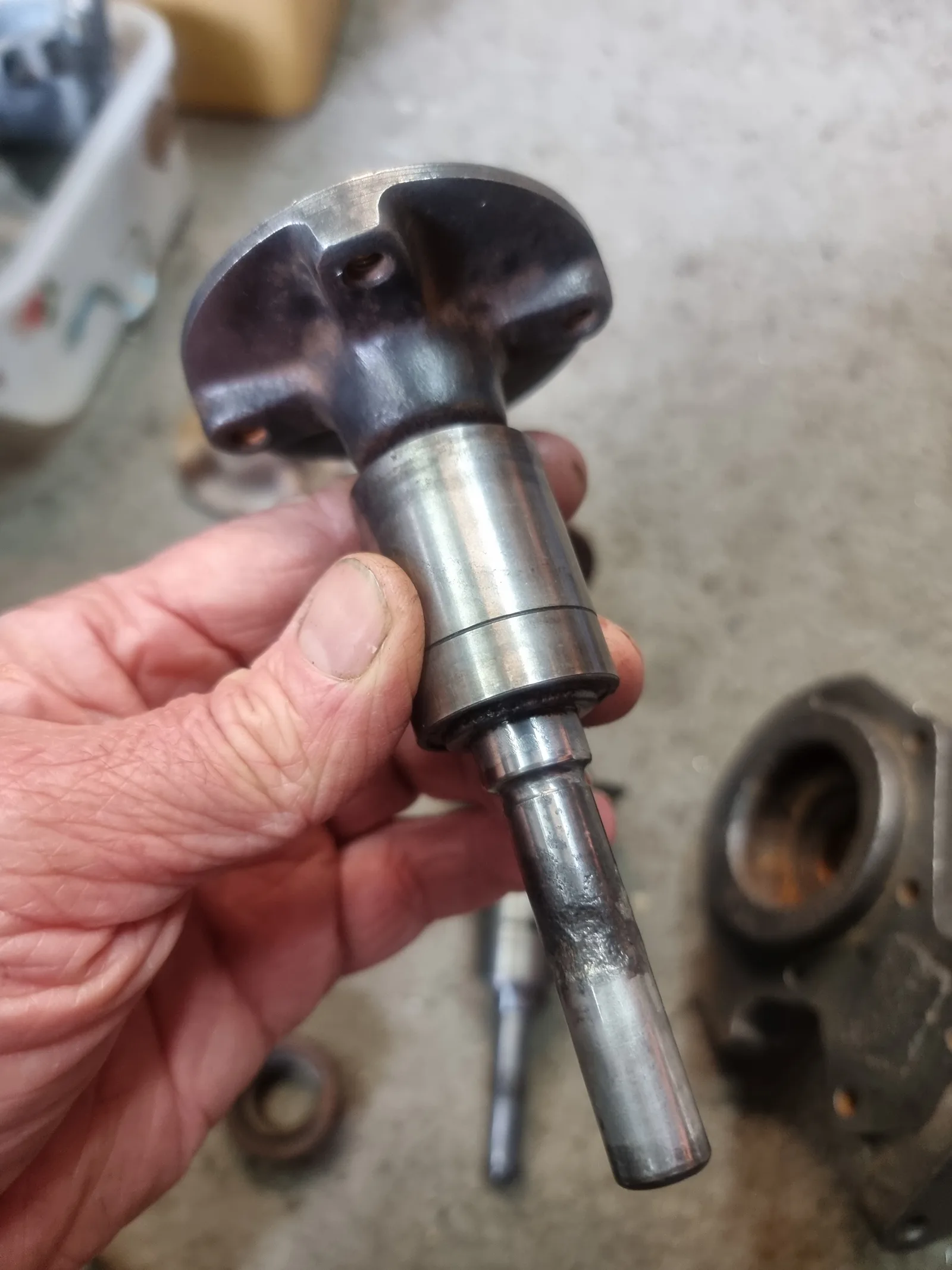
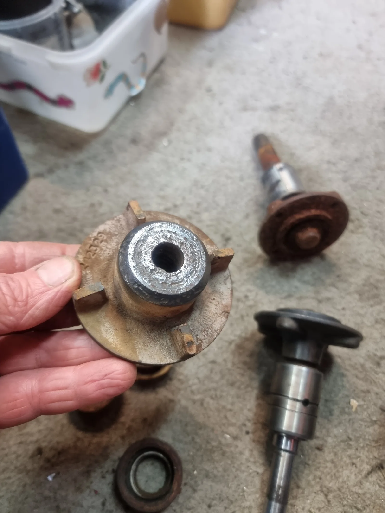
First, remove the impeller, spindle, and bearing unit using a pin punch or press.
Notes
Begin by removing the location bolt on the side of the pump body, which holds the bearing and spindle in place. Note that the bearing and spindle form a single unit and cannot be separated. Use a pin punch and hammer to drive the spindle bearing and drive flange out from the front of the pump body. Take care not to crack the impeller, as it is cast iron and fragile. Depending on the pump's age and corrosion, a puller may be attempted to remove the impeller, though this method may fail. Once the spindle and bearing unit with the drive flange is removed, support the drive flange in a 40mm pipe to press the shaft out.
Illustrations / Images
Step 2
Inspection
Purpose
Check the pump body and impeller for excessive corrosion and ensure the impeller was not damaged during disassembly.
Notes
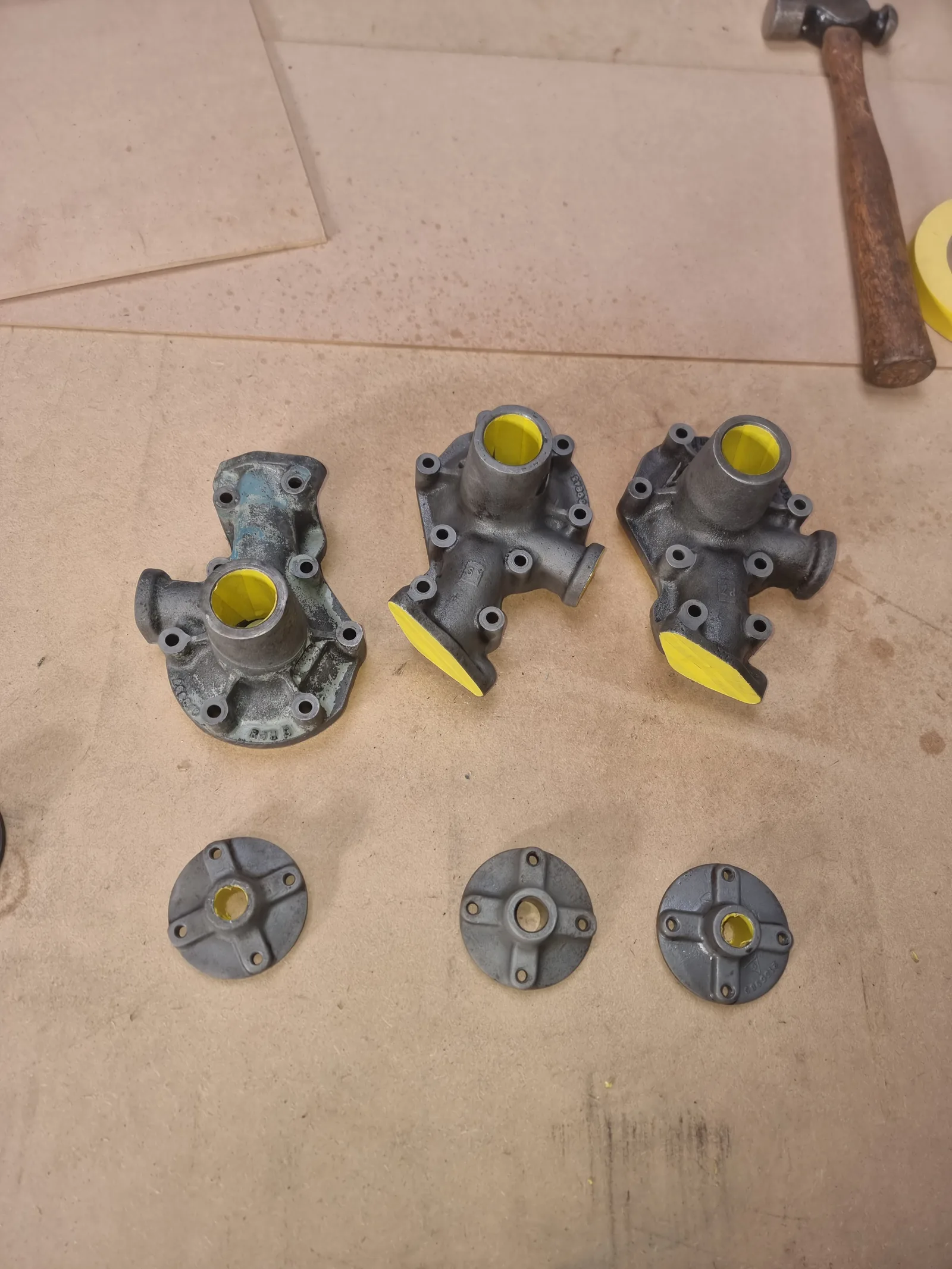
Some pumps may have significant corrosion; a small amount is normal. If the components clean up well, rebuilding can proceed. Ensure the recess where the mechanical seal presses in is clean and free of corrosion. Make sure the weep hole is clear and scrape away any corrosion to allow water to drain rather than collect. Optionally, repaint the pump body if needed.
Illustrations / Images
Step 3
Machining / Surface Prep
Purpose
Trim the spindle shaft to the correct length.
Method
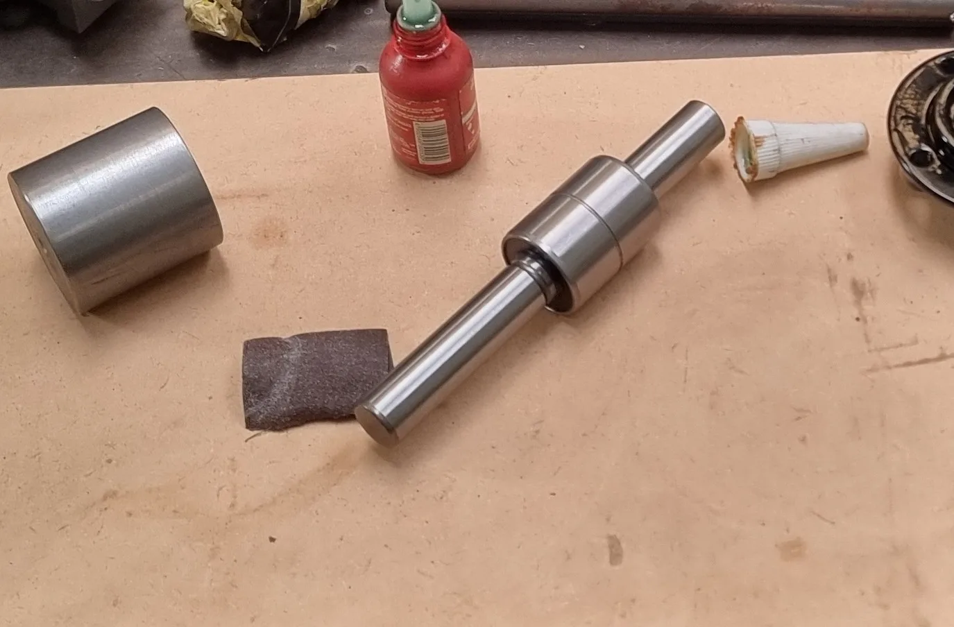
Spindle shafts are not hardened and can be cut with a hacksaw.
Notes
After cutting the shaft to size, file or machine a small chamfer on the outside edge.
Illustrations / Images
Step 4
Bearing Instalation
Purpose
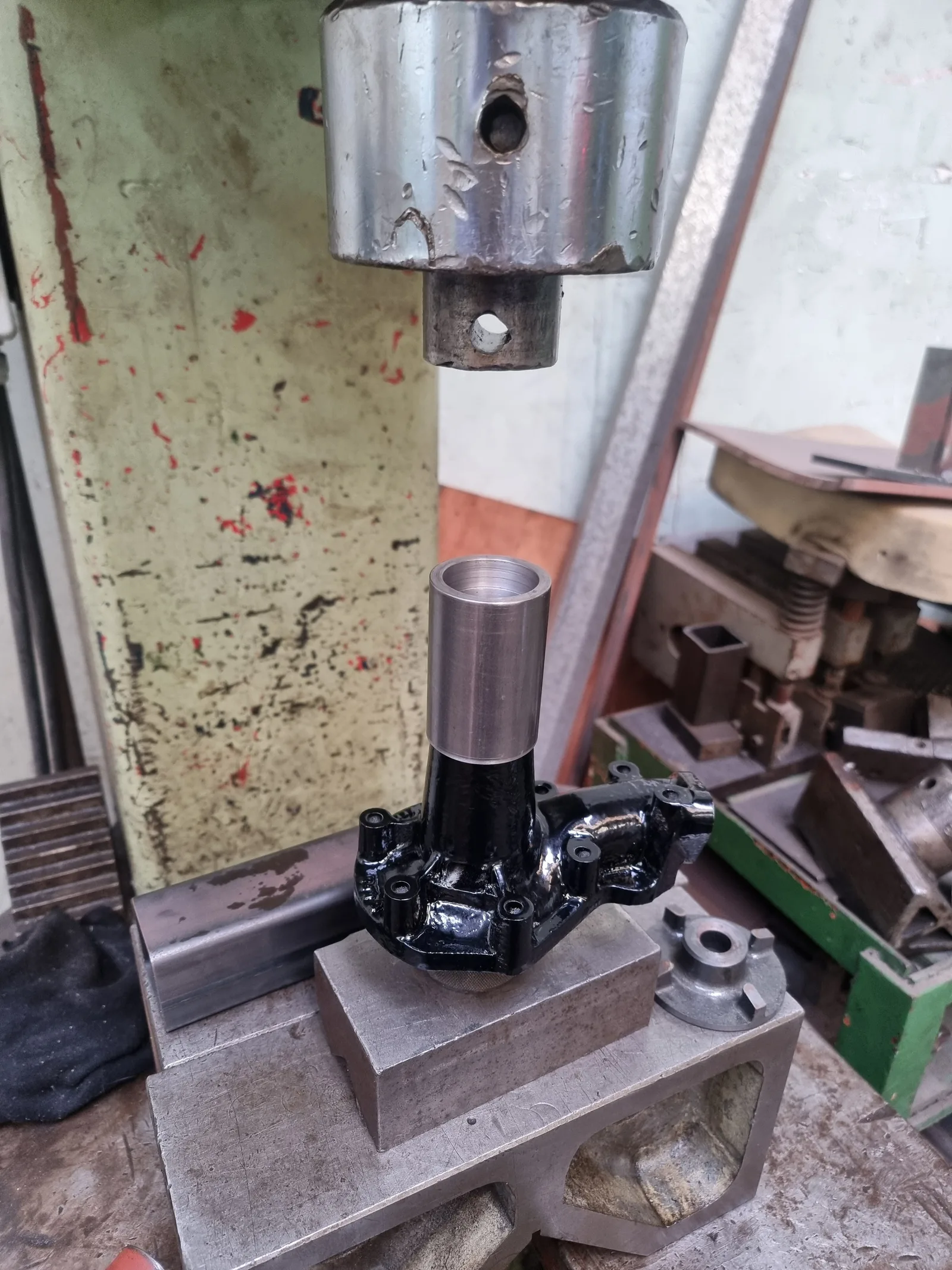
Press the bearing and spindle into the pump body.
Method
Press the short end of the spindle (the side that was shortened) into the pump body first.
Notes
Ensure the spindle and bearing are pressed in square (perpendicular to the pump body). Off-the-shelf bearings do not have a machined location hole; if concerned, use Loctite 609 bearing retaining compound to prevent bearing movement.
Illustrations / Images
Step 5
Drive Flange assembly
Purpose
Assemble the drive flange to the correct set dimension.
Method
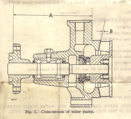
Press the drive flange onto the spindle to the specified dimension. Refer to your workshop manual for the correct measurement for your Series pump. The dimension is measured from the mounting face of the pump body to the front mounting face of the drive flange.
Notes
Important: There are two different styles of water pumps. Ensure you use the correct set dimension for your pump body:
- 1948-49 vehicles with cast iron fan pulley: A = 104mm
- 1948-49 vehicles with pressed steel fan pulley: A = 107mm
- 1948-50 vehicles with double groove fan pulley: A = 107mm
- 1950-53 vehicles with single groove fan pulley: A = 105mm
- 1954-58 Land Rover 2L: A = 105mm
The spindle must be supported to avoid pressure on the bearings.
- Diesel model water pump set dimension: 86.36mm
Illustrations / Images
Step 6
Mechanical Seal
Purpose
Press the mechanical seal into place.
Method
Use special tool 100-2186 to support the seal's outer and inner flange during installation.
Notes
Lightly smear Loctite 609 bearing retaining compound on the outside of the mechanical seal where it presses into the pump body. Support the drive flange and spindle to prevent movement or force on the bearings.
Step 7
Impeller assembly
Purpose
Assemble the impeller and check the impeller clearance.
Method
Press the impeller onto the spindle similarly to the mechanical seal installation.
Notes
Carefully press the impeller onto the spindle. The correct position is determined by checking the clearance between the impeller and the pump body, which should be 0.4–0.5mm. Use feeler gauges to verify this measurement.
Step 8
Final checks
Purpose
Perform final checks to ensure the pump is ready for use.
Notes
Verify the following:
1. Drive flange set dimension matches your vehicle's specification.
2. Impeller clearance is between 0.4 and 0.5mm.
3. The pump turns freely and smoothly.
Illustrations / Images
Technical Notes
Clearances
Impeller clearance for all vehicles: 0.5mm.
Drive flange set dimensions:
- 1948-49 vehicles with cast iron fan pulley: 104mm
- 1948-49 vehicles with pressed steel fan pulley: 107mm
- 1948-50 vehicles with double groove fan pulley: 107mm
- 1950-53 vehicles with single groove fan pulley: 105mm
- 1954-58 Land Rover 2L: 105mm
Lessons Learned
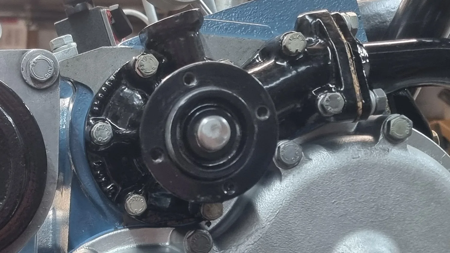
It is beneficial to dry fit your water pump to ensure all pulleys align perfectly with the main drive pulley on the harmonic balancer.
Downloads & References
- Special tool - 100-2186 can be ordered here: https://twomaxengineering.com/engineering/products